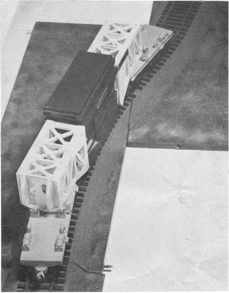
Although the car is 90 feet between coupler faces when loaded with a 28-foot long transformer, it moves through sharp curves like a 50-foot long box car. |
 |
A new type of railroad car, in which the lading itself becomes part of the car, will soon be rolling over the nation's railroads.
Designed by an Erie shipper, the Westinghouse Electric Corp., to transport the super-size transformers that American power companies need to serve the country's expanding economy, the car was developed by R. L. Bean, engineer at Westinghouse's transformer division at Sharon, with the help of John Kolb of the Greenville Steel Car Co.
Although the car is 90 feet between coupler faces when loaded with a 28-foot long transformer, it moves through sharp curves like a 50-foot long box car. |
|
Many problems were met and solved in the design of the car, Bean told members of the American society of Mechanical Engineers last month when he read a paper at their annual convention.
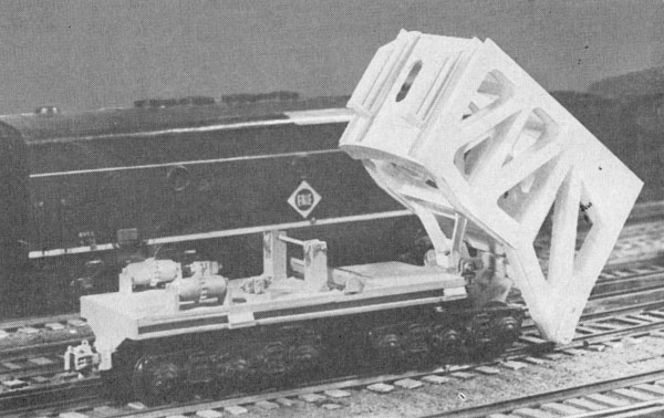
No crane is needed to load the giant-size transformer. The car can pick it up if the load is blocked up on the track. Unloading, too, can be done without the help of crane or derrick. |
 |
One of the problems was that of the brake line-and hereafter every transformer of a size to be shipped by this car will have a length of 1 1/4 inch extra strong pipe as part of its permanent case.
But that was the smallest of the problems that Bean and Kolb faced in the design of the car, need for which was recognized early in 1957, when transformers became so large that they had to be shipped in sections, with resultant problems in reassembly.
Those transformers had a capacity of 260,000-kva at 345,000 volts; today transformers with a capacity of 315,000-kva are in service, and capacities of 500,000-kva are contemplated - so large that they would cause problems even on the high and wide Erie.
The early 1957 transformer had a shipping weight of 400,000 pounds; soon, perhaps by the end of the year, transformers may weigh 500,000 pounds, be 28 feet long, but will travel in one piece, as part of the new car, which will offer no more difficult problems in switching and routing than a normal 50-foot boxcar.
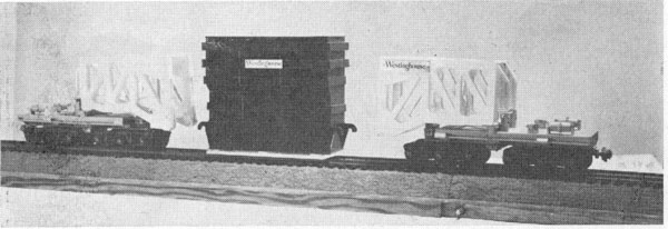
Loaded and ready to rool the transformer has become part of the car, and can be handled through yards and across bridges without special routing. |
 |
The new car uses the structural strength of the transformer itself - and big transformers have strong, heavily - built cases - to act as the center part of the car. Basically, the idea is this: attach wheel trucks to either end of the transformer.
Obviously, the primary benefit comes from being able to lower the load to within a few inches of the rails. A second benefit of nearly equal value is that the center of gravity is lowered an equal amount, giving a much more stable load than is possible with former methods of loading. (The first big transformer shipped this year had to ride on a heavy - duty car with a floor 49 inches above the rails.)
Many special problems were met with in designing the car.
Besides the transformer weight of 500,000 pounds, a train load of 150,000 pounds pulling and 375,000 pounds buffing was allowed for. Then too, there are the problems of side sway, and stresses on curves.
One circumstance favored the designers: In normal manufacture transformers of this size are lifted and carried by the four corners of the bottom section, so this section of the case is normally strong. Only slight modifications were needed in the design of the upper part of the case to make it strong enough to bear the compressive force of the trusses and the buffing forces it will withstand in train operation.
But the car halves required a great deal more development and analysis.
The simplest solution would have been to build the bridge - like trusses pivoted at the centers of the car halves. But that would have limited the width of the load, because, as the car went around curves or through switches, it would have acted like a car 70 feet long.
|
Jacks built into the car make it possible to tilt the trusses like this one to pick up or set down the load. |
 |
So it was decided to pivot the trusses at the inner ends of the car halves. And then the problems multiplied.
For the load is so heavy that if its weight was carried on a flat metal bearing surface its action would be so stiff that the car would be in danger of derailing on curves. Too, where changes of grade were met on straight track, the bearings would be subjected to bending stresses.
The problem of sliding friction was met by designing a roller - bearing pivot, with conical rollers, because cylindrical rollers would skid under the conditions the car will experience. Both the truss bearing surface, and the bearing surface in the car half must be machined to fit the conical rollers.
That solved the problem of going around curves. The problems involved in going up and down hill were met by mounting the whole bearing upon a cylindrical bearing running across the car on each of the two car halves.
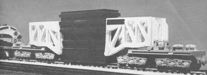
When traveling without a load, the two car halves hook together at the bottom of the trusses, and the tops of the trusses are held apart with steel spacers.
The car will be simple to load if an overhead crane of sufficient capacity is on hand.
When empty, the car's two halves are locked together like this for return. |
|
But that brought up another problem-how to load the transformer, and unload it, where no such crane was available.
That was solved by building two 100-ton and two 30-ton jacks into each car half. The 30-ton jacks can maneuver the trusses; the 100-ton jacks can lift truss and load together.
In the absence of a crane, the transformer can be blocked up on any straight stretch of track, so that its bottom is 12 inches off the rails. Then the two halves of the car are brought up to it, and hooked on, using the small jacks. Then the big jacks lift the load off the cribbing, the cribbing is removed, and the jacks withdrawn.
As soon as the air - line connection is made the load is ready to roll. Unloading without a crane is just as simple, the designers say.