The following pictues and text were taken from the October 1957 issue of Modern Railroads Magazine.
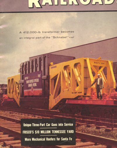
Three-Part Car Makes First Trip
The nation's first three part railroad car is now in operation.
The three-part car, was designed by Westinghouse Electric Corp. and built by Greenville Steel Car Co., Greenville, Pa., made its first trip with a 412,000 lb Westinghouse autotransformer as its middle section. The trip started August 6, 1957, from Sharon, PA., bound for the Ohio Power Co's station at Foster, W. Va.
Previous to the construction of the new car, large capacity transformers were made with removable top sections, so that they could be loaded upon available flat cars and remain within weight and clearance limits.
This method was not only costly to both the manufacture and the purchaser, but also involved the risk of having the transformer open during assembly in the field and the possibilities of fitters not familiar with the transformer doing the critical reassembly work.
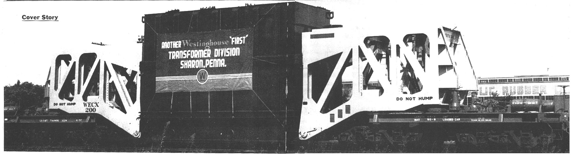
The Schnabel car consists of two identical sections. Each section is about 30 ft long and is made up of a truss, underframe and two six wheel trucks. The transformer is slung between the sections to make up the complete car. For the return trip, the sections are hooked together at the bottom of the trusses, and the tops of the trusses are held apart by means of steel spacers in order to operate the unit without the transformers.
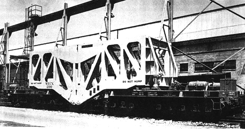
Close coupled for the return trip, the trussed are pinned together at the bottom and hedl apart at the top by spacers. The end trusses return to next assignment as a unit.
Two Ways to Handle Transformers
A transformer, the third part of the car, can be loaded in one of two ways. It can be handled with an overhead crane of sufficient capacity or it can be placed on a section of straight track and handled with jacks and cribbing. Where no crane is available, loading and unloading is made possible by two 100-ton jacks, and tow 30-ton jacks built into the trusses of each section of car.
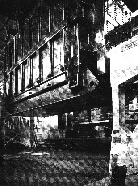
Overhead crane lowers load into position between trusses. Where overhead cranes are not available for loading, loads can be placed on straight section of track and be supported cribbing. Jacks contained on end sections position the sections for applications of pins.
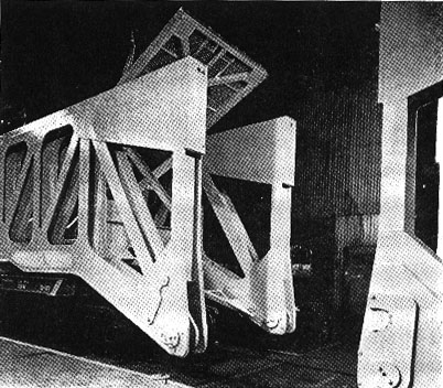
The transformer is placed on cribbing on a straight section of track, so that the bottom of the transformer is 12 inches from the rail. The two sections of the car are brought up to it and hooked on, using the 30-ton jacks. The two 100-ton jacks then raise the entire load off of the cribbing. The track is then cleared and the transformer is lowered to the transporting position.
One end truss has been pinned to the load, and the other has been brought up read to position and pin. The bottoms are in tension, the tops are in compression.
Unloading is done by a reverse process.
Although the car is about 92 feet long when loaded, it can negotiate the same curvature as a standard 50-ft boxcar. This is accomplished by an offset pivot and traversing load centers. The offset pivot point is made possible by a swiveled drawbar connecting between the truss and the underframe. The traversing load centers presented considerable trouble in their development. A flat metal bearing surface, although the simplest solution, would have required too much lateral force to overcome the sliding friction. The problem was solved by an arrangement of tapered roller bearings and a hardened conical surface on the underside of the truss. The hardened surface of the truss allowed the roller nest to be the part which would wear first since it is the most easily replaced.
The primary benefit of the new car is that the transformer can be lowered to within 6 in. of the rail, whereas the bed of a heavy-duty flatcar with sufficient capacity for such a load would be about 30 in. above the rail. The center of gravity of the load is lowered by the same amount when using the car.
It is believed that the new car will reduce installation cost and delivery time for the customers because unit weights up to 500,000 lbs. can be shipped as a single piece of equipment. Before the construction of this car, the size of the transformer ol load was limited by the height and weight restrictions imposed by existing railroad rolling stock.
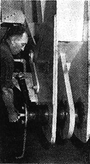
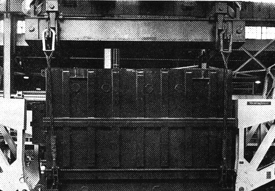
Removable sections of cross bracing is raised to permit the lowering of transformers with out damage to external equipment.
|
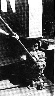
Attaching pin is being drawn to accept load. Each pin is 8 in. in diameter. Total load is carried on the pins.
|
Load is lifted clear by two 100-ton jacks on each end truss. Trusses are positioned by two 30-ton jacks per truss. |